On completion of this module, you will be able to:
- Understand what is Digital Communication ?
- Learn basic elements of a Digital Communication system
- Learn different communication channel and their characteristics
- Understand mathematical models for communication channel
- Know the advantages & disadvantages of Digital Communication system
- Learn electromagnetic bands
- Define Sampling
- Explain Sampling Theorem for low pass signal and band pass singal
Introduction to Communication
- Communication is the process of transferring a message or information from source to destination or one point ot other point through a channel
- Based upon the message signal, communication systems can be classified into two types:
1. Analog Communication System and
2. Digital Communication System
Analog Communication System
- Analog communication systems use analog signals to transmit the message
- Analog signals vary continuously with time and have continuously varying amplitude for each time instant.for example - Voice
Digital Communication System
- The physical transfer of data (a digital bit stream) over a point-to-point or point-to-multipoint communication channel is called Digital Communication
- In Digital Communication, information is transmitted in digital form, from one or more sources to one or more destinations

Fig. 1(a): Analog and Digital Signal. Fig. 1(b): Analog to Digital Converter
Examples of Digital Communication are :
- Wireless communication systems ( Cellular wireless communication systems )
- E-mailing ( Computers )
- Texting ( Cell Phones )
- Online games ( Web Kinz, Club Penguin )
- Walkie-talkies
- Videos containing information
- Online announcements etc
Elements of Digital Communication System: Basic elements of communication systems are
- Information Source
- Source Encoder
- Channel Encoder
- Modulator
- Communication Channel
- Demodulator
- Channel Decoder
- Source Decoder
- Output (User)

Fig. 2: Elements of Digital Communication Systems
Information Source :
- The source of information can be digital or analog. In Digital Communication the signal produced by this source is converted into digital signal consists of 1′s and 0′s. For this we need source encoder.
Source Encoder :
- The process of efficiently converting the output of source into a sequence of binary digits is known as source encoding or data compression.
Channel Encoder :
- Channel encoder introduces some redundancy in the binary information sequence which can be used at the receiver to overcome the effects of noise and interference encountered in the transmission through the channel For example: take m bits of the information sequence and map that m bits to unique n bit sequence called Code Word. The amount of redundancy introduced is measured by the ratio n/m and the reciprocal of this ratio (m/n) is known as Rate of Code or Code Rate.
Digital Modulator :
- Digital modulator converts the binary sequence, which is received from the channel encoder, into electric signals, so that we can transmit them on channel. The digital modulator maps the binary sequences into signal wave forms For example: if we represent 1 by sin x and 0 by cos x then we will transmit sin x for 1 and cos x for 0.
Channel :
- The channel is used for transmitting signals from the transmitter to receiver. In traditional telephony, this channel is wired, for wireless system, this channel consists of atmosphere, there are optical channels, under water acoustic channels etc.
Digital Demodulator :
- The digital demodulator receives transmitted signal contains the information which is corrupted by noise and reduces the waveform to the sequence of numbers that represents estimates of the transmitted data symbols.
Channel Decoder :
- Channel decoder reconstructs the original information sequence from the knowledge of the code used by the channel encoder and the redundancy contained in the received data .
Source Decoder :
- If an analog signal is desired then source decoder tries to decode the sequence from the knowledge of the source encoding methods
Output :
- Finally we get the desired signal in desired format analog or digital
Communication Channel and Their Characteristics :
Communication Channels :
- Wire Line Channels
- Fiber Optical Channels
- Wireless Electromagnetic Channels
- Under Water Acoustic Channels
Wire line channels operate at few kHz to several hundreds of kHz frequency

Fig. 3: wire line channel
Fiber Optical Channels provides bandwidth in the magnitude several times higher than that of wire line channel

Fig. 4: Fiber Optical Channel
Wireless Electromagnetic Channels operates in the range of 10kHz to =~ 100 GHz, this is further categorized as long wave radio, short wave radio, microwave radio as they operates in radio frequency they are also known as radio or radio channel

Fig. 5: Wireless Electromagnetic Channels
Under Water Acoustic Channels operates at extremely low frequencies

Fig. 6: Under Water Acoustic Channels
Storage Channels like magnetic tapes, magnetic disks, CD, DVD etc.

Fig. 7: Storage Channels
Mathematical Models for Communication Channels
The Additive Noise Channel
- Where, α is the attenuation factor
- s(t) is the transmitted signal
- n(t) is the additive random noise process(a random process, usually Gaussian)
r (t) = α s(t) + n(t)

Fig. 8: additive noise channel
The Linear Filter Channel
- To satisfy the specified bandwidth limitations
- Where c(t) is the impulse response of the linear filter, and * denotes convolution
r (t) = s(t) * c(t) + n(t)
r (t) = ∫∞∞ c(τ)s(t-τ)dτ+n(t)

Fig. 9: Linear filter channel with additive noise
The Linear Time-Variant Filter Channel
- Where, c(τ ;t) is the response of the channel time t due to an impulse applied at time (t-τ)
r (t) = s(t) * c(τ ;t) + n(t)
r (t) = ∫∞∞ c(τ ;t)s(t-τ)dτ+n(t)

Fig. 9: Linear time-variant filter channel with additive noise
Advantages and Disadvantages of Digital Communication
Advantages of Digital Communication
- AM & FM signals become corrupted over much short distances as compared to digital signals
- In digital signals, the original signal can be reproduced accurately
- It is harder to separate noise from an analog signal while noise is easily separated from a digital signal
- By suitable receiver AM and FM signals can be received by any one while digital signals can be coded so that only the intended person can receive it
- AM and FM transmitters are real time systems i.e. they can be received only at the time of transmission while digital signals can be stored at the receiving end
- Error detecting and error correcting codes improve the system performance by reducing the probability of error
- By using spread spectrum technique we can avoid signal jamming in Digital Communication
- Noise Separation :It is harder to separate noise from an analog signal while noise is easily separated from a digital signal

Fig. 10: Regenrative Pulses

Fig. 11: Noise seperation
Disadvantages of Digital Communication
- Large bandwidth required :- The transmission of digitally encoded analog signals occupies significantly more bandwidth as compare to simply transmitting the original analog signals. Data compression may be employed
- Complicated signal processing :- Analog signal must be converted to digital codes before transmission and converted back to analog form at the receiver, thus require additional encoding (A / D) and decoding (D / A) circuitry
- Need for precision timing :- Bit, character, frame synchronization needed
- Higher complexity
Analog to Digital Converter
- An analog to digital converter (abbreviated ADC, A/D or A to D) is a device which converts a continuous quantity to a discrete digital number. The reverse operation is performed by a digital to analog converter (DAC).
- Typically, an ADC is an electronic device that converts an input analog voltage (or current) to a digital number proportional to the magnitude of the voltage or current.
- The input to the A/D converter is a voltage:- A/D converters may be designed for voltages from 0 to 10v, from -5 to +5v, etc., but they almost always take a voltage input. (Some rare exceptions occur with current inputs!) In any event, the input is an analog voltage signal for most cases.
- The output of the A/D converter is a binary signal, and that binary signal encodes the analog input voltage. So, the output is some sort of digital number.

A/D converters are electrical circuits that have the following characteristics
Sampling
- Continuous time signal cannot be processed in the digital processor or computer
- We need to convert continuous time signal into discrete time signal. The process by which the continuous time signal is converted into a discrete time signal is called sampling.
- Sampling is the first step in the process of converting a continuous analog signal to a sequence of digital numbers
- Analog signal is converted into a corresponding sequence of numbers that are usually uniformly spaced in time this process is known as sampling process
- Sampling is the first process performed in A/D conversion, and it converts a continuous time signal into a discrete time signal or a sequence of numbers.
- Illustration of the ideal sampling process is shown in the figure.
- Types of Sampling : -
1. Instantaneous (Ideal) sampling
2. Natural sampling
3. Flat-top Sampling


Fig. : Sampling.

Fig. : Types of Sampling: (1)Ideal Sampling (2) Natural Sampling (3) Falt-top Sampling.
Ideal Sampling
- Ideal sampling also called Instantaneous sampling or Impulse sampling.
- Since the width of pulses is almost zero, the ideal sampling gives train of impulses in x𝛅(t)
- Representation of x(t) in terms of its samples


Natural Sampling
- In natural sampling the pulse amplitude takes the shape of the analogue waveform for the period of the sampling pulse.
- Here the sampling waveform s(t) consists of a train of pulses having width τ and separated by the sampling time TSS.
- The baseband signal m(t), and the sampled signal s(t)m(t) is shown in the figure in which sampled signal consists of a sequence of pulses of varying amplitude whose top follow the waveform of the signal m(t).
- The original signal can be retrieved by passing the samples through an ideal low-pass filter with cutoff at the frequency fM, where fM is the highest frequency component of the signal.

Flat-top Sampling
- Flat-Top sampling also called the rectangular pulse shaping.
- In a Flat-top sampling scheme, the amplitude of a pulse after sampling is kept constant and is related to the value of signal m(t) at a pre-decided instant within the pulse duration τ .
- The pulse width , though small, is considered to be significant compared to the rise and fall times of the pulses to avoid unnecessary mathematical complexity
- Since τ is non zero, the top of a sampled pulse does not follow x(t) during τ.


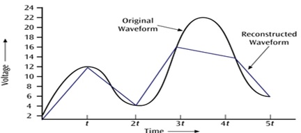
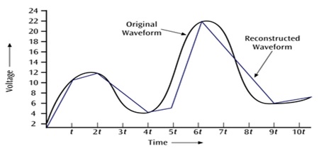
Sampling Theorem for Low Pass signal
- A band limited signal of finite energy, which has no frequency components higher than W Hz, is completely described by specifying the value of the signal at instant of time separated by 1/2W seconds and
- If a band limited signal of finite energy, which has no frequency components higher than W Hz may be completely recovered from the knowledge of its samples taken at the rate of 2W samples per second
Combined statement of sampling theorem can be written as,
- A continuous time signal can be completely represents in its samples and recovered back if the sampling frequency fs >= 2W. Where fs is the sampling frequency and 'W' is the maximum frequency present in the continuous time signal
Nyquist Sampling Theorem
- Statement: The sampling frequency should be at least twice the highest frequency contained in the signal or in mathematical terms:
- Where fs represents the sampling frequency and W represents the highest frequency contained in the signal
- Nyquist Rate: When the sampling rate becomes exactly equal to 2W samples/sec for a given bandwidth of W Hz, then it is called Nyquist rate
- Nyquist Interval: It is the time interval between any two adjacent samples when sampling rate is Nyquist rate.
fs >= 2W
Nyquist Rate = 2W Hz
Nyquist Interval = 1/2W seconds
Aliasing :
- When the sampling rate is lower than or equal to the Nyquist rate, a condition defined as under sampling
- Under sampling causes frequency components that are higher than half of the sampling frequency to overlap with the lower frequency components
- As a result, the higher frequency components roll into the reconstructed signal and cause distortion of the signal. This type of signal distortion is called aliasing
- Aliasing can be avoided by using the following methods:-
1. Sampling rate should be greater than equal to 2W. When the sampling rate is made higher than 2W, then the spectrum will not overlap and there will be significant gap between the individual spectrums.
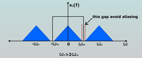
2. Strictly band limit the signal to W in case of fS = 2W there can be few components higher than 2W. This component creates aliasing. So a low pass pre alias filter is used before sampling the signal.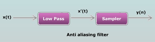

Fig. : Aliasing
Sampling of Band Pass Signal
- Statement: The band pass signal x(t) whose maximum bandwidth is 2W Hz can be completely represented in its sampled form and recovered from its samples if it is sampled at the minimum rate of twice the bandwidth.
fS>=2W
PCM System
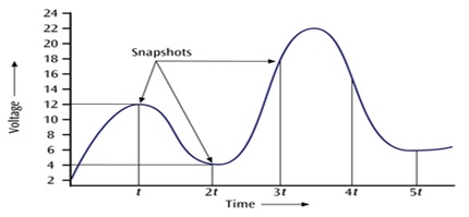
- Pulse code modulation (PCM) is essentially analog-to-digital conversion of a special type where the information contained in the instantaneous samples of an analog signal is represented by digital words in a serial bit stream.
- The analog waveform is sampled at specific intervals and the “snapshots” are converted to binary values.
- When the binary values are later converted to an analog signal, a waveform similar to the original results.
- The more snapshots taken in the same amount of time, the better the resolution.
- Block diagram of PCM system is shown below
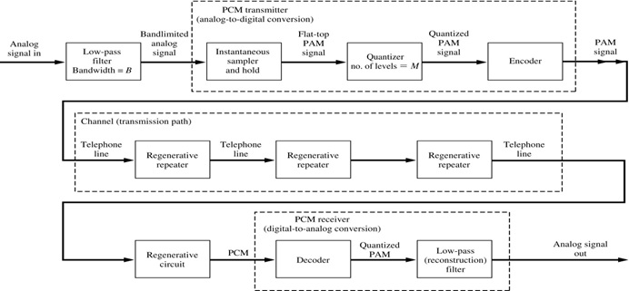
PCM Transmitter
- PCM consists of three steps to digitize an analog signal:
1. Sampling
2. Quantization
3. Binary encoding - Before the sampling, we have to filter the signal to limit the maximum frequency of the signal as it affects the sampling rate.
- Filtering should ensure that we do not distort the signal, i.e. remove high frequency components that affect the signal shape.
- Sampling:
- Sampling makes the signal discrete in time.
- Analog signal is sampled every Ts secs. Ts is referred to as the sampling interval.
fs = 1/T s is called the sampling rate or sampling frequency. - There are three sampling methods:
1. Ideal - an impulse at each sampling instant
2. Natural - a pulse of short width with varying amplitude
3. Flattop - sample and hold, like natural but with single amplitude value - According to the Nyquist theorem, the sampling rate must be at least 2 times the highest frequency contained in the signal.
- Quantization:
- Quantization makes the signal discrete in amplitude.
- Sampling results in a series of pulses of varying amplitude values ranging between two limits: a min. and a max.
- The amplitude values are infinite between the two limits.
- We need to map the infinite amplitude values onto a finite set of known values.
- This is achieved by dividing the distance between a min. and a max. into L zones, each of height D.
D = (max - min)/L - The midpoint of each zone is assigned a value from 0 to L-1 (resulting in L values)
- Quantization is the process of “rounding off” a sample according to some rule. for example: Suppose we must round to the nearest tenth, then: 3.752 = 3.8 and 0.001 = 0
- Encoding:
- It combines the process of sampling and quantization and translates the discrete set of sample value to a more appropriate form of signal.
- Representing the discrete set in particular arrangement is called code and one of the discrete events in a code is called a code element or symbol.
- In binary code, each symbol may be either of two distinct values (0 and 1) such as the presence or absence of pulse.
- In ternary code, each symbol may be one of three distinct values, and so on for other codes.
- In the binary number system, each bit has place-value that is a power of 2, as shown in the table for the case of n=3.

Line Code
- A line code is the code used for data transmission of a digital signal over a transmission line. This process of coding is chosen so as to avoid overlap and distortion of signal such as inter-symbol interference.
- There are three types of line coding :-
1. Unipolar
2. Polar
3. Bi-polar - Unipolar signaling is also called as On-Off Keying or simply OOK. The presence of pulse represents a 1 and the absence of pulse represents a 0. There are two variations in Unipolar signaling −Non Return to Zero (NRZ) and Return to Zero (RZ).
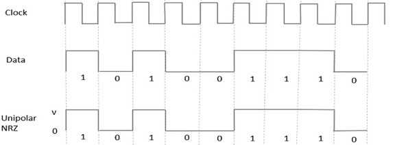
Unipolar NRZ
- In this type of unipolar signaling, a High in data is represented by a positive pulse called as Mark, which has a duration T0 equal to the symbol bit duration. A Low in data input has no pulse. The following figure clearly depicts this.
Unipolar RZ
- In this type of unipolar signaling, a High in data, though represented by a Mark pulse, its duration T0 is less than the symbol bit duration.
- Half of the bit duration remains high but it immediately returns to zero and shows the absence of pulse during the remaining half of the bit duration. It is clearly understood with the help of the following figure.

Polar Signaling
- There are two methods of Polar Signaling. They are −
1. Polar NRZ
2. Polar RZ
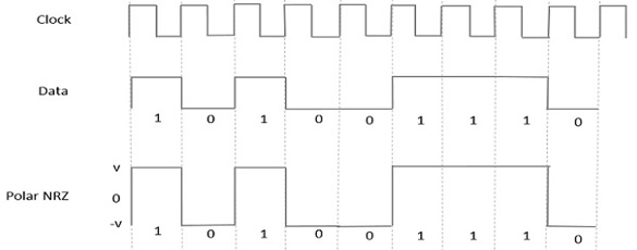
Polar NRZ
- In this type of Polar signaling, a High in data is represented by a positive pulse, while a Low in data is represented by a negative pulse. The following figure depicts this well.
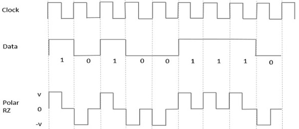
Polar RZ
- In this type of Polar signaling, a High in data, though represented by a Mark pulse, its duration T0 is less than the symbol bit duration. Half of the bit duration remains high but it immediately returns to zero and shows the absence of pulse during the remaining half of the bit duration.
- However, for a Low input, a negative pulse represents the data, and the zero level remains same for the other half of the bit duration. The following figure depicts this clearly.
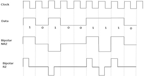
Bipolar Signaling
- This is an encoding technique which has three voltage levels namely +, - and 0. Such a signal is called as duo-binary signal.
- An example of this type is Alternate Mark Inversion. For a 1, the voltage level gets a transition from + to – or from – to +, having alternate 1s to be of equal polarity. A 0 will have a zero voltage level.
- We have learnt the difference between NRZ and RZ. It just goes in the same way here too. The following figure clearly depicts this.
- The above figure has both the Bipolar NRZ and RZ waveforms. The pulse duration and symbol bit duration are equal in NRZ type, while the pulse duration is half of the symbol bit duration in RZ type..